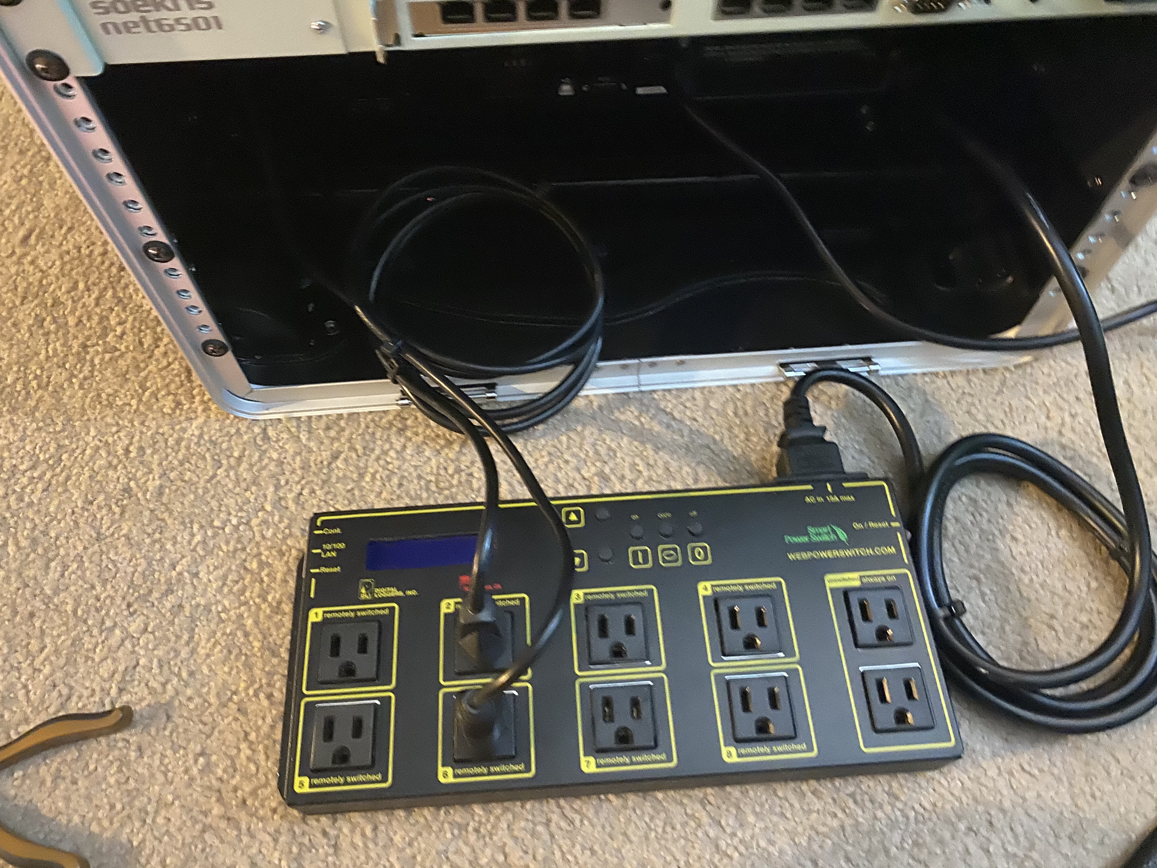
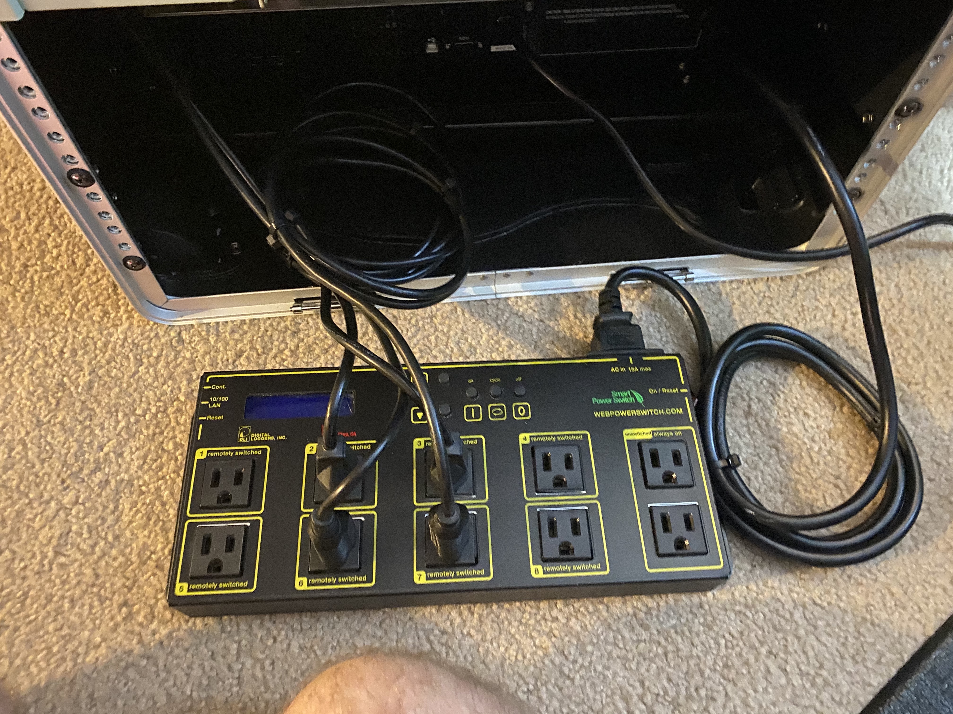
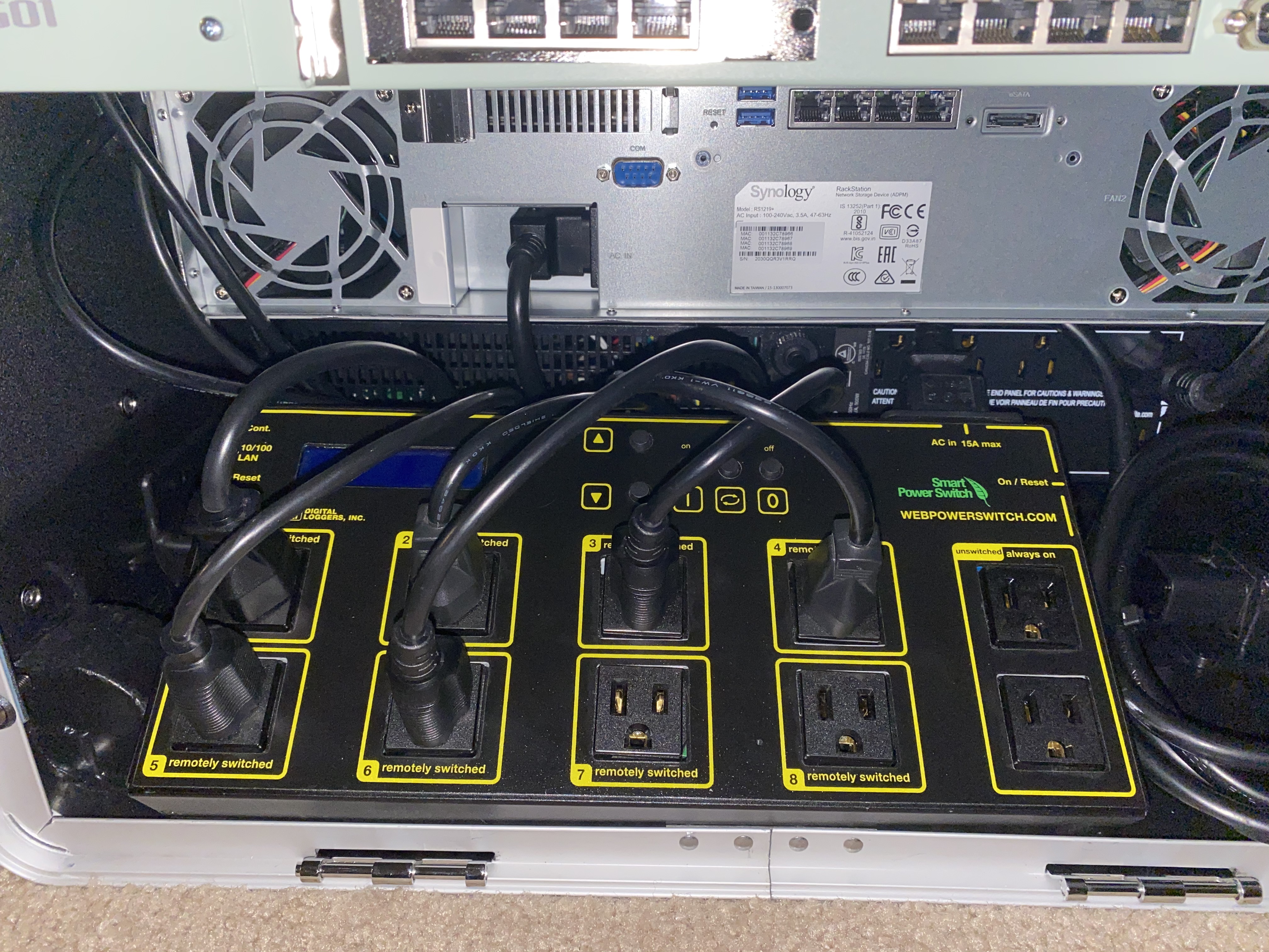
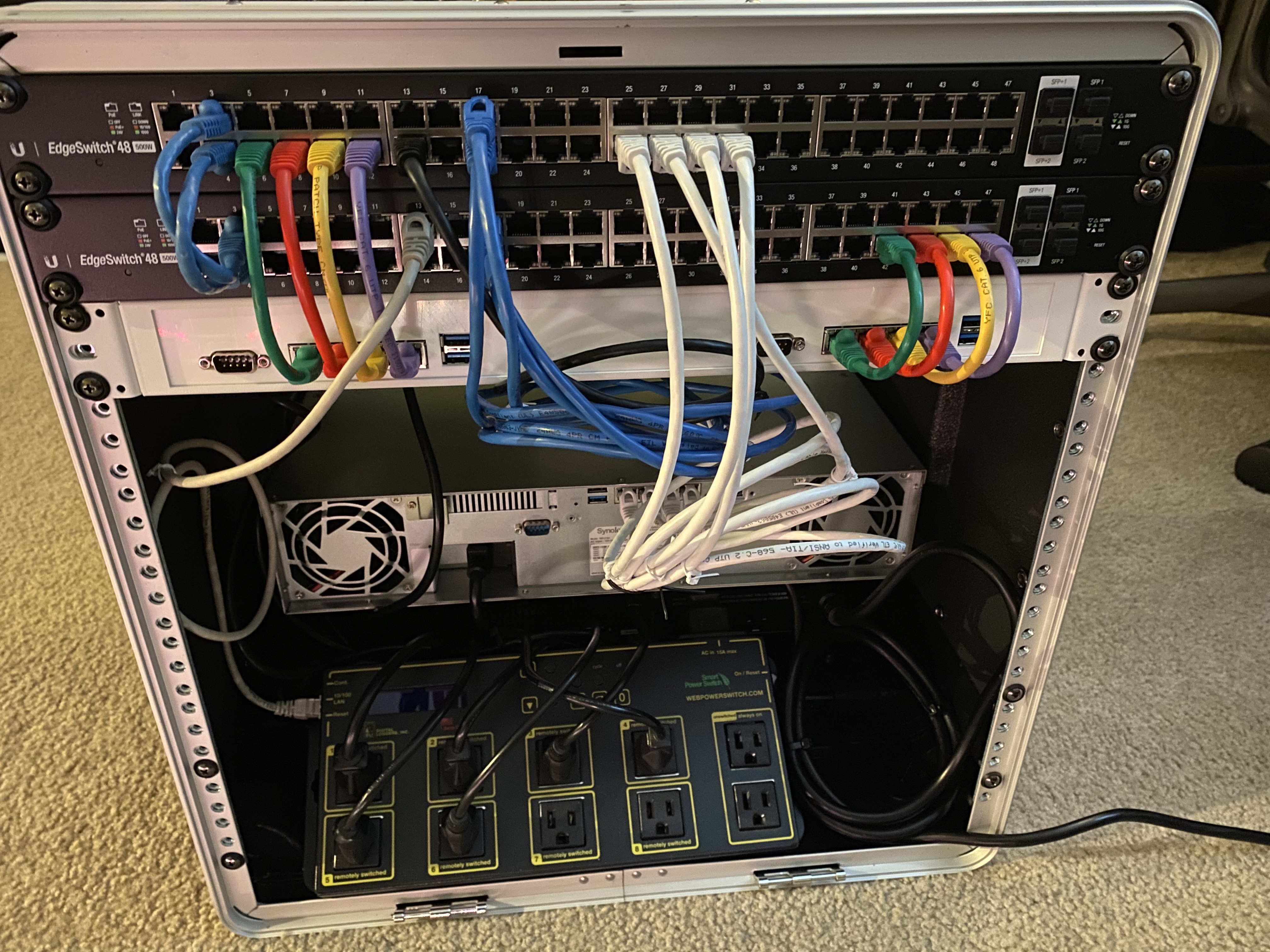
I like to use a Web Power Swiitch whenever I cable up things to power. It has a rudimentary ping capability that can power cycle a port if it loses network connectivity to it. A handy feature if you're not going to have physical access to a machine that might be having network problems and just needs a reboot to get it going again. Getting the power cables all shoved out of the way without restricting air flow too much is a challenge.
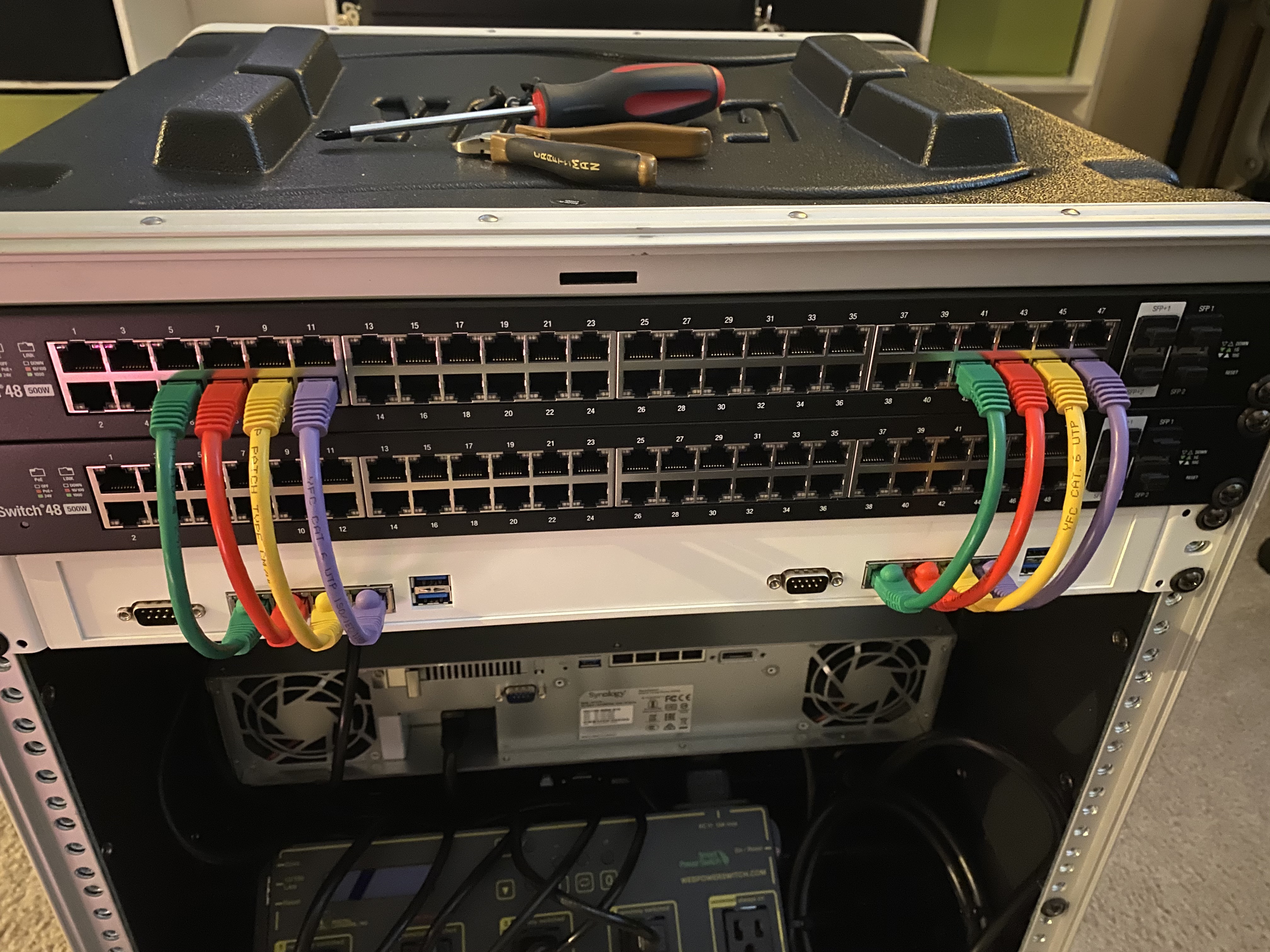
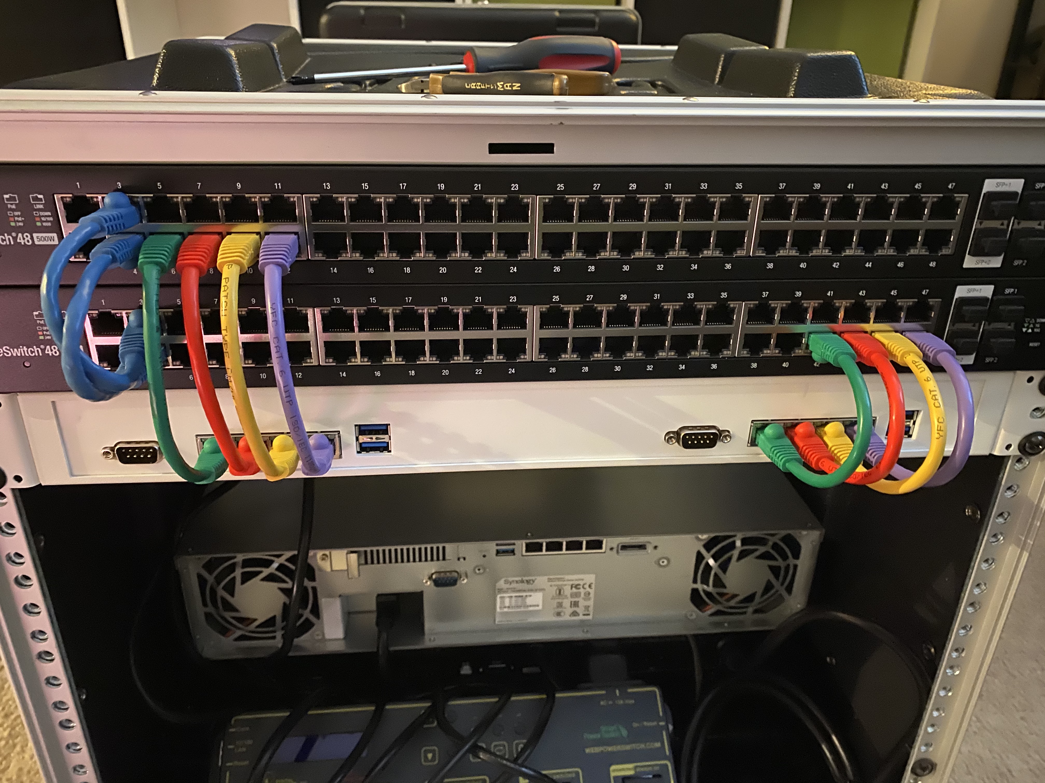
For the network, I like to color code my cables for which traffic the port will be carrying. It costs a little more finding the right color cable in the right length, but it saves me headaches when I'm trying to figure out things in a hurry. I wire them close to the physical location for the APU4 boards, and the top and bottom switches will be configured identically, so that should a switch fail, the cables in one can be moved to the same port on the other switch. This means only 50% of the ports on either switch will be in use when both switches are functional. This also means a single switch must have enough ports to handle all devices in the crate. We lose some efficiency here for the redundancy.
This exhausts around 32 ports, leaving 16 ports for whatever we might imagine later. This is why 48-port switches were chosed instead of 24 port ones.
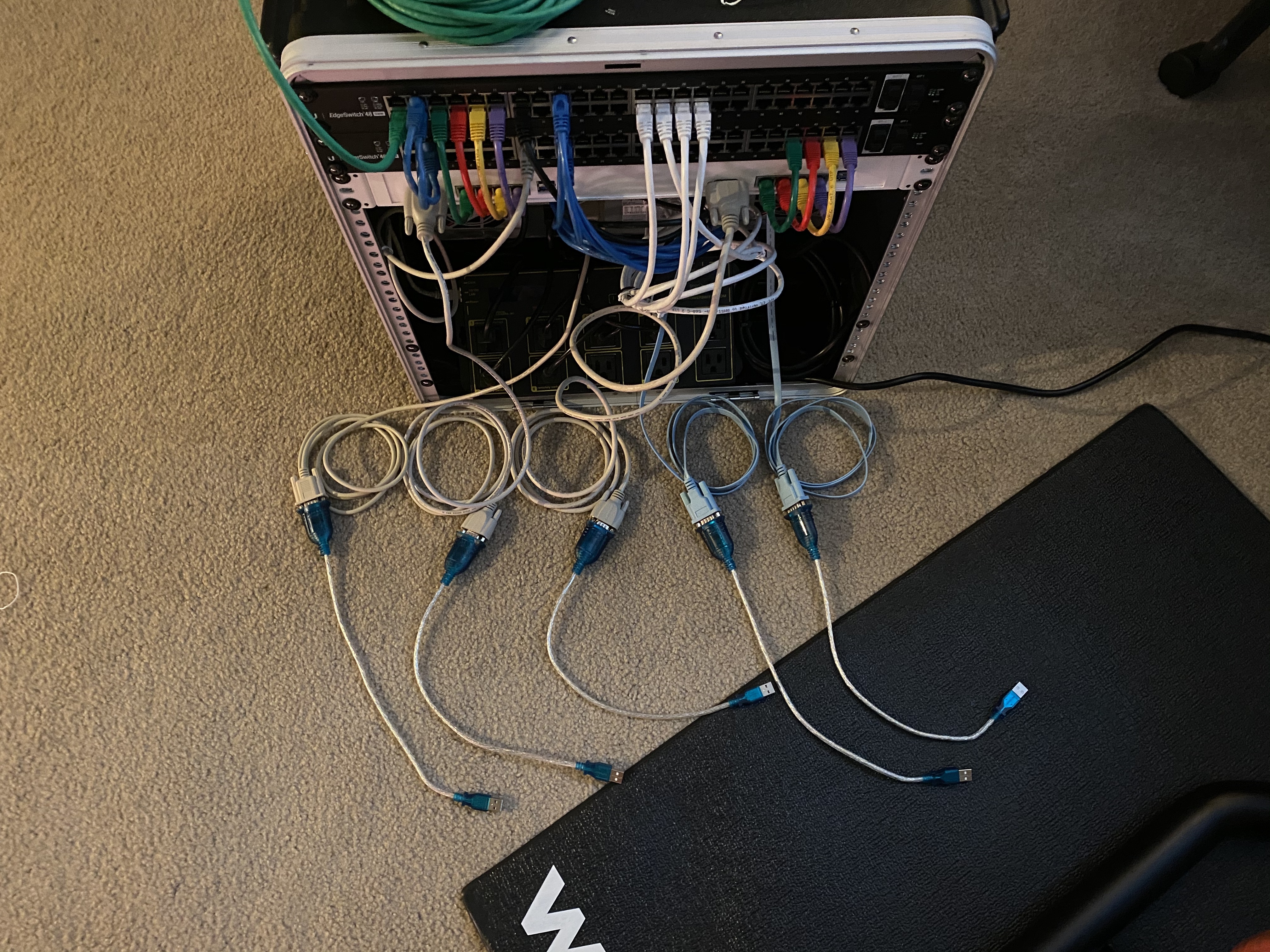
For the serial port setup, I need:
I cabled the cisco rollover cables to the edge switches, and the null-modem cables to the NAS, and the consoles on the two APU4s. Then plugged the USB side into the 7 port USB switch, and used the last two ports to power the raspberry pi and the monitor from the Kano.me kit.
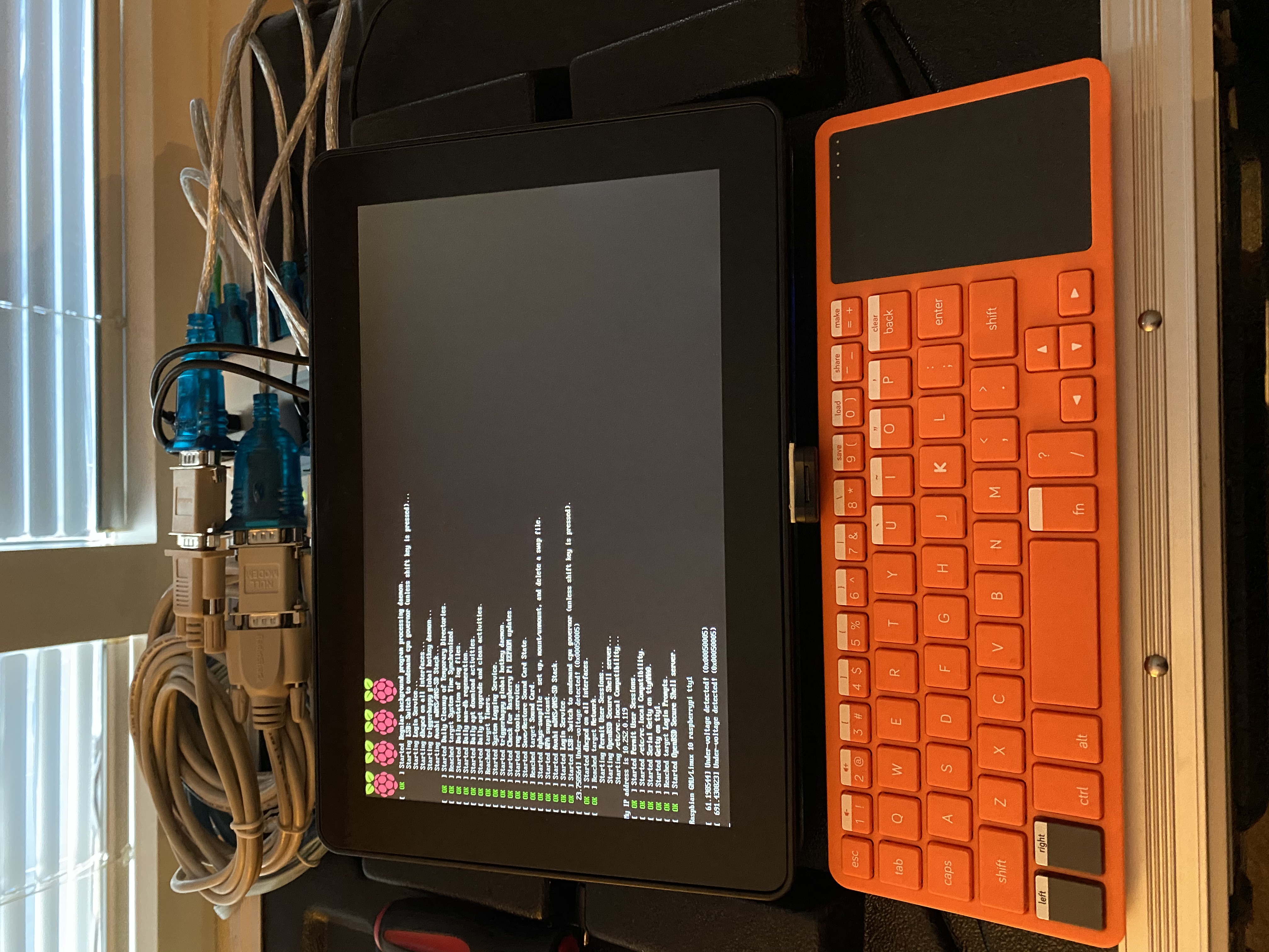
At this point everything is connected and ready to lay out operating systems and configure with our deployment node.